In modern photovoltaic systems, microinverters play a vital role. Compared to traditional centralized inverters, microinverters, with their unique design, can convert the direct current of each solar panel into alternating current, thereby improving the overall efficiency and flexibility of the system. Working independently, the microinverters not only maximize the output of each PV module but also ensure system stability and high energy output under the influence of shadows, dirt, or other environmental factors.
With the progress of photovoltaic technology, the importance of communication monitoring is becoming increasingly prominent. Communication monitoring enables users to obtain the operating status of photovoltaic systems in real time, monitor electrical energy output, and identify potential failures. This data acquisition and analysis capability is critical to the maintenance and management of the system, helping users take preventive action before problems occur, thereby reducing downtime and maintenance costs.
This paper aims to analyze four main microinverter communication monitoring methods: WiFi, Sub-1G, PLC, and RS485. Through an in-depth analysis of these four mainstream communication monitoring methods, we will explore their advantages and disadvantages and applicable scenarios to help users make wise choices according to their needs.
WiFi communication monitoring
Working principle
WiFi communication monitoring is connected to the router through the built-in WiFi module of the microinverter to achieve data transmission and real-time tracking. The microinverter transmits the operating data of the photovoltaic system (such as power generation, system status, etc.) to the user's smartphone or computer through WiFi signals. Using 2.4G channels for communication, this frequency band is widely used due to its good coverage and universal support.
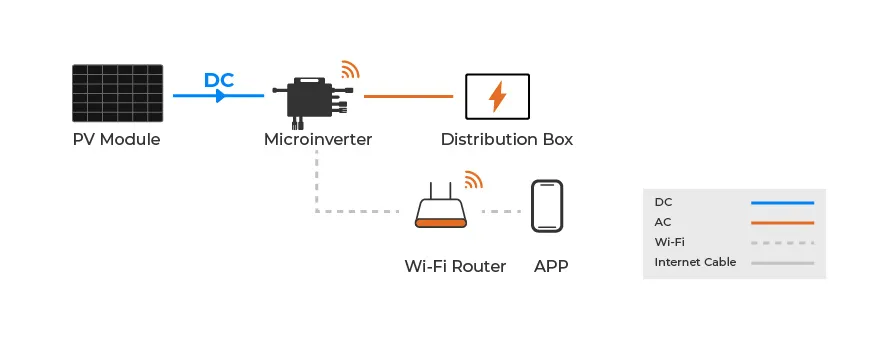
The use of 2.4G channels and its advantages
The 2.4G channel is one of the standard bands for WiFi and has the following advantages:
Wide coverage: The signal penetration ability is strong and can cover a large area.
High device compatibility: Almost all WiFi devices support this band, and users do not need to worry about device incompatibility when setting up and connecting.
Good transmission stability: Under the right environment, the 2.4G band can still provide stable signal transmission.
advantage
Easy installation and configuration: One of the biggest advantages of WiFi communication monitoring is its ease of use. Users simply connect the WiFi module of the microinverter to a home or business network without complicated cabling or expertise.
Realization of real-time monitoring function: Through the WiFi connection, users can monitor the operating status of the system in real-time, view power generation data, and performance analysis. This real-time feedback helps users keep track of how the system is working and react quickly in the event of a failure.
shortcoming
Dependence on the home network: The effectiveness of WiFi communication monitoring depends heavily on the stability of the home or business network. Network signal instability or congestion can cause data transmission delays or interruptions.
Limitations in signal strength: Despite the wide coverage of the 2.4G signal, the signal strength can weaken in some environments, resulting in unstable connections.
Signal instability
WiFi signals may be interfered with by other electronic devices, affecting the stability and reliability of communication.
Overall, WiFi communication monitoring provides a convenient solution for users who want real-time monitoring with easy installation. However, users also need to consider their dependence on the network environment and potential signal problems when using.
Sub-1G communication monitoring
Working principle
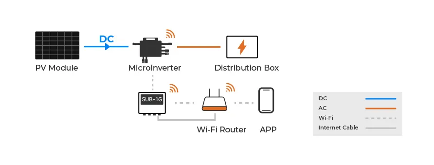
Sub-1G communication monitoring uses wireless signals in the Sub-1G band to connect the microinverter to a specialized Sub-1G connector. The microinverter has a built-in wireless communication module, which transmits data through a low-frequency signal (such as 433MHz, 868MHz, or 915MHz) and a Sub-1G connector, which then transmits data to the router through WiFi to achieve connection with user devices (such as smartphones or computers).
The workflow of this architecture is as follows:
Data acquisition: The microinverter collects the operating data of the photovoltaic system, such as power generation and system status.
Wireless transmission: The microinverter wirelessly sends data to the Sub-1G connector via the Sub-1G band. Due to the low-frequency characteristics of the Sub-1G band, there is less interference in the transmission process and the signal stability is stronger.
WiFi transmission: The Sub-1G connector then transmits the received data to the router through the WiFi signal to realize the connection to the user's device.
Real-time monitoring: Users can monitor the operating status and performance analysis of the photovoltaic system in real-time through the corresponding application.
Advantages
Low interference: Due to the lower frequency used, the Sub-1G band has less interference and a more stable signal compared to the more crowded 2.4G band.
Strong penetration: Low-frequency signals have better penetration ability, can effectively penetrate walls and obstacles, and are suitable for a variety of complex environments.
shortcoming
Challenges during installation
The installation of Sub-1G communications monitoring usually requires specialized knowledge. Users need to have certain basic knowledge of wireless communication when setting up to ensure the normal operation of the system.
The need for additional equipment
When Sub-1G communication is adopted, additional receiving devices (such as Sub-1G connectors) are usually required, which may increase the overall cost of the system and bring additional setup and maintenance work to the user.
The possibility of increased costs
In addition to equipment costs, the installation and maintenance of Sub-1G communication systems may also require additional inputs, especially for users who do not have the relevant technical background, which may result in a higher total cost of ownership.
In summary, Sub-1G communication monitoring through its stability and strong penetration, is suitable for a variety of complex environment applications. However, users should also be aware of potential challenges such as installation difficulty and cost when considering this approach.
PLC communication monitoring
Working principle
PLC (Power Line Communication) technology uses the existing power line as the data transmission medium to connect the microinverter to the PLC module. The PLC module converts the operating data (such as power generation and system status) sent by the microinverter into high-frequency signals through the power line and transmits them to the PLC receiver through the power grid. The receiver then connects the data to the router via a network cable, thus connecting it to the user's device (such as a smartphone or computer) for remote monitoring.
The core of the PLC communication mechanism lies in the following aspects:
Signal modulation: The PLC module built into the microinverter modulates the data into a high-frequency signal, which is superimposed on the low-frequency alternating current of the power line.
Grid transmission: The modulated signal is transmitted through existing power lines, utilizing the infrastructure of the grid without the need for additional wiring.
Signal demodulation: The PLC receiver receives the signal on the power line, demodulates it, and transmits the data to the router through the network cable to realize the connection with the user device.

advantage
Economy and convenience without additional wiring
The biggest advantage of PLC communication is that it can make full use of the existing power line infrastructure, and users do not need to carry out additional wiring, which significantly reduces installation costs and time, and improves convenience.
Resistance to external signal interference
PLC technology is more resistant to external interference than other wireless communication methods. Because the data is transmitted through the power line, it is less affected by wireless signal interference in the environment, which ensures the stability of data transmission.
shortcoming
The influence of power grid quality on signal transmission
The effectiveness of PLC communication largely depends on the quality of the power grid. If there are many other appliances on the line, noise, voltage fluctuations, or other power problems that may exist in the grid can affect the transmission quality of the signal, which can lead to data loss or delay.
Limitations of applicable scenarios
PLC technology may have compatibility problems in older power grids, especially in environments with poor power lines or more electrical equipment, which may lead to unstable signal transmission. Therefore, when choosing a PLC communication scheme, users need to consider the specific situation of their power grid to ensure the reliability of communication.
Installation mode of the signal collector
Buckle method: This method is relatively simple, the user only needs to buckle the signal collector on the socket of the power line, which is fast and convenient.
Wiring mode: This mode is more complex and involves direct wiring of power lines, requiring users to have certain electrical knowledge and skills, and the installation process is relatively time-consuming and may have security risks.
In summary, PLC communication monitoring realizes an economical and practical communication solution by using the existing power line network, which is suitable for scenarios where additional wiring is inconvenient. However, when choosing this scheme, users should also pay attention to the quality of the grid and the limitations of the applicable scenarios, as well as the complexity of the installation method to ensure the stable operation of the system.
RS485 Communication Monitoring
Working Principle
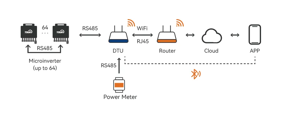
RS485 communication uses differential signaling to transmit data between devices over a shared medium, typically a twisted pair cable. In the case of microinverters, RS485 is used to connect each inverter to a central Data Transmission Unit (DTU). The RS485 module within the microinverter sends operational data (such as power generation and system status) over the communication bus. The DTU collects this data and transmits it to the monitoring system via a network cable, enabling remote monitoring on a user device (like a smartphone or computer).
The core mechanism of RS485 communication involves the following aspects:
Differential Signaling: RS485 transmits data by creating a voltage difference between two wires (A and B). This method helps to cancel out noise and maintain data integrity over long distances.
Multi-device Communication: RS485 allows multiple microinverters to be connected on the same communication bus, making it ideal for systems with numerous devices needing centralized monitoring.
Centralized Data Collection: The DTU acts as the central data collector, receiving data from all connected inverters via the RS485 bus. It then transmits this data to the router through an Ethernet cable, making it available for monitoring on user devices.
Advantages
Long-distance and Stable Transmission One of the major advantages of RS485 is its ability to transmit data over long distances (up to 1200 meters) without significant signal degradation. This is particularly useful in solar installations where inverters may be located far from the central monitoring system.
Resistance to Electromagnetic Interference (EMI) RS485’s use of differential signaling makes it highly resistant to electrical noise and electromagnetic interference (EMI), which is crucial in environments where inverters and power lines may generate significant interference.
Multi-device Support RS485 supports multi-drop configurations, meaning multiple microinverters can be connected to the same bus. This makes it ideal for solar systems where many inverters need to communicate with a central monitoring system.
Compatibility with Harsh Environments The robust design of RS485 communication ensures stable performance even in harsh environments, such as industrial settings or outdoor solar power plants, where temperature fluctuations and environmental conditions could affect other communication methods.
Disadvantages
Complex Installation and Setup RS485 communication systems require proper termination, grounding, and bus topology configuration. This can increase the complexity of installation compared to wireless or simpler communication methods. Improper setup may result in data transmission errors.
Limited Data Rate RS485’s data rate decreases as the transmission distance increases. While it’s suitable for monitoring applications that don’t require high-speed data transfer, it may not be ideal for more complex data or real-time communication needs.
Requires Professional Installation Installing RS485 correctly requires a certain level of expertise, particularly in configuring bus topology and ensuring proper termination. This adds to the installation time and cost as professional electricians or technicians may be needed.
Impact of Distance and Signal Integrity
RS485 is designed for long-distance communication, but signal quality can degrade over very long distances or in environments with excessive noise. Termination resistors are often required at the ends of the RS485 bus to minimize signal reflection, ensuring cleaner and more accurate data transmission.
Installation Modes for the Signal Collector
Buckle Installation: This method involves attaching the RS485 signal collector directly to the communication cable. It’s a simple and quick installation method, ideal for small systems where ease of setup is a priority.
Direct Wiring Installation: In this method, the RS485 signal collector is wired directly into the communication network. This method offers greater stability but requires more skill and is time-consuming. It’s often used in larger installations where long-term reliability is critical.
Summary
RS485 communication monitoring offers a reliable, long-distance solution for data transmission in solar energy systems. Its ability to support multiple devices and resist interference makes it a strong choice for centralized monitoring of microinverters. However, its installation complexity and the need for proper termination and grounding mean it is best suited for environments where a professional setup is feasible. Additionally, while RS485 is stable and efficient, users must consider the distance and data rate limitations, ensuring that the system is designed to support the specific requirements of the installation.
By leveraging the robustness of RS485, users can build a cost-effective, efficient monitoring network for solar energy systems, especially in installations where wiring and environmental conditions make wireless or PLC solutions less suitable. However, users must weigh these benefits against the technical expertise and installation effort required to ensure stable, long-term operation.
Communications Monitoring Performance Evaluation and Rating
The following comparison evaluates the four communication methods of WiFi, PLC, Sub-1G, and RS485, and rates them based on three key factors: cost, signal stability, and ease of installation. Through the intuitive star rating, we can see the performance of each communication method under different factors.
|
|
Cost
|
Signal stability
|
Installation
|
|
WiFi
|
✮✮✮✮✮
|
✮✮✮
|
✮✮✮✮✮
|
|
PLC
|
✮✮✮✮
|
✮✮✮
|
✮✮✮✮
|
|
Sub-1G
|
✮✮✮✮
|
✮✮✮✮
|
✮✮✮✮
|
|
RS485
|
✮✮✮
|
✮✮✮✮✮
|
✮✮✮
|
- WiFicommunication monitoring: The microinverter comes with a WiFi module that can be directly connected to the router, greatly reducing the cost. However, the signal stability of WiFi is poor, especially in long distances or in interference environments. In terms of installation, it does not require complex operations, is extremely simple and fast, and is suitable for small photovoltaic systems that do not require high stability.
- Communication monitoring: PLC needs to be equipped with a PLC signal collector, resulting in relatively high costs. Since other devices in the power line may generate noise, the accuracy of signal transmission may be disturbed, resulting in reduced stability. In addition, PLC installation involves the connection of multiple devices, and the construction complexity is medium.
- Sub-1G communication monitoring: This solution also requires a signal collector, so the cost is relatively high. Because it uses different frequency bands for transmission, it is less affected by external interference, so the signal stability is better. However, similar to PLC, the installation of Sub-1G also requires the connection of multiple devices, and the installation process is slightly complicated.
- RS485 communication monitoring: The RS485 system requires a dedicated RS485 line and a DTU, which increases the overall cost. However, because it uses a line connection method, the stability of signal transmission is very high and is almost not affected by external interference. However, the installation process of RS485 is relatively complicated and requires professional personnel to carry out wiring and debugging, and the construction difficulty is relatively large.
This analysis not only rates the four communication monitoring methods of WiFi, PLC, Sub-1G, and RS485 based on three key factors: cost, signal stability, and installation difficulty, but also delves into their specific performance in different usage scenarios, through a comprehensive analysis of factors such as stability and ease of construction.
|
|
Balcony
|
Rooftop
|
Small-scale industry and commerce
|
Large-scale industry and commerce
|
|
WiFi
|
Excellent
|
Excellent
|
Not recommended
|
Not recommended
|
|
PLC
|
Not recommended
|
Excellent
|
Good
|
Good
|
|
Sub-1G
|
Not recommended
|
Good
|
Excellent
|
Good
|
|
RS485
|
Not recommended
|
Good
|
Excellent
|
Excellent
|
Advantages of TSUN microinverter
1. Full-scenario communication monitoring solution
TSUN microinverters provide comprehensive communication monitoring solutions that can easily cope with various application scenarios. Whether it is a small residential photovoltaic system or a large industrial project, TSUN can ensure the stability and reliability of data transmission through flexible communication methods. This diverse communication support provides users with a high degree of scalability and facilitates efficient monitoring and management in different environments.
2. Built-in WiFi module and RS485 interface to meet the needs of all scenarios
The significant advantage of the TSUN microinverter is its built-in WiFi module and RS485 interface, which provides users with flexible communication options. The built-in WiFi module allows the system to quickly connect to the router without additional wiring, making it suitable for rapid deployment in small photovoltaic systems. The RS485 interface provides more stable long-distance communication support for large and complex environments and is especially suitable for scenarios with higher signal reliability requirements.
By combining these two communication methods, TSUN microinverters can easily meet the needs of photovoltaic systems of different sizes and complexity, providing comprehensive remote monitoring solutions.
|

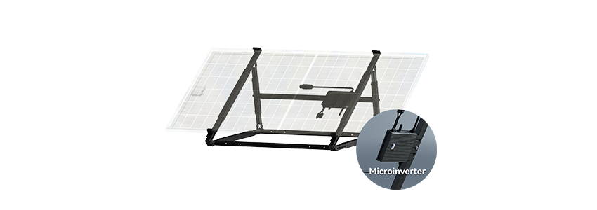
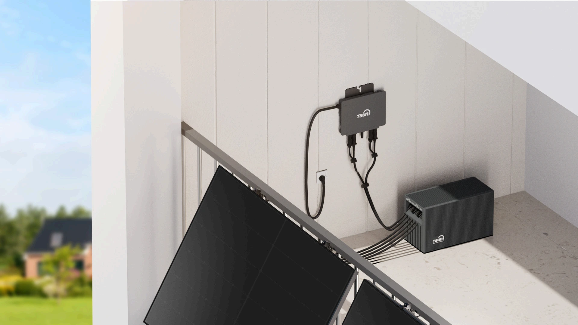
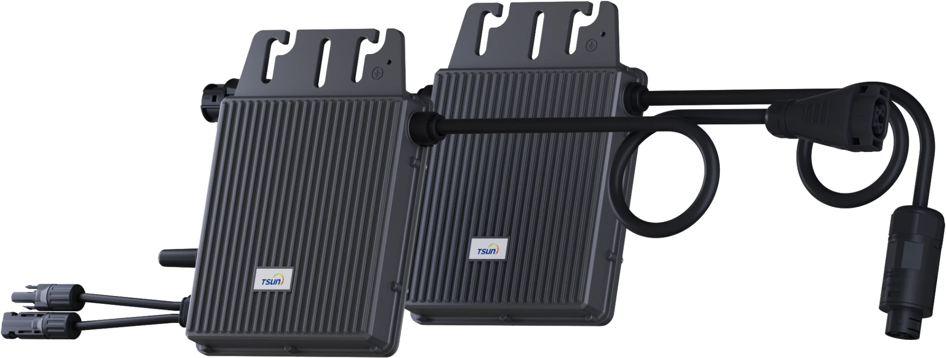
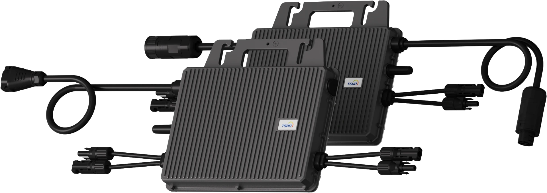
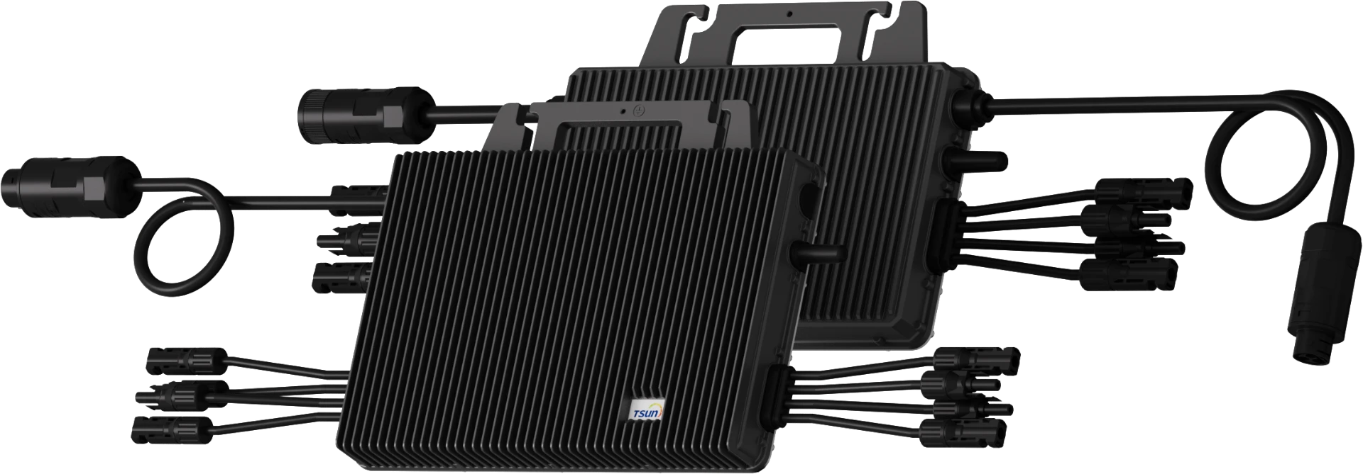
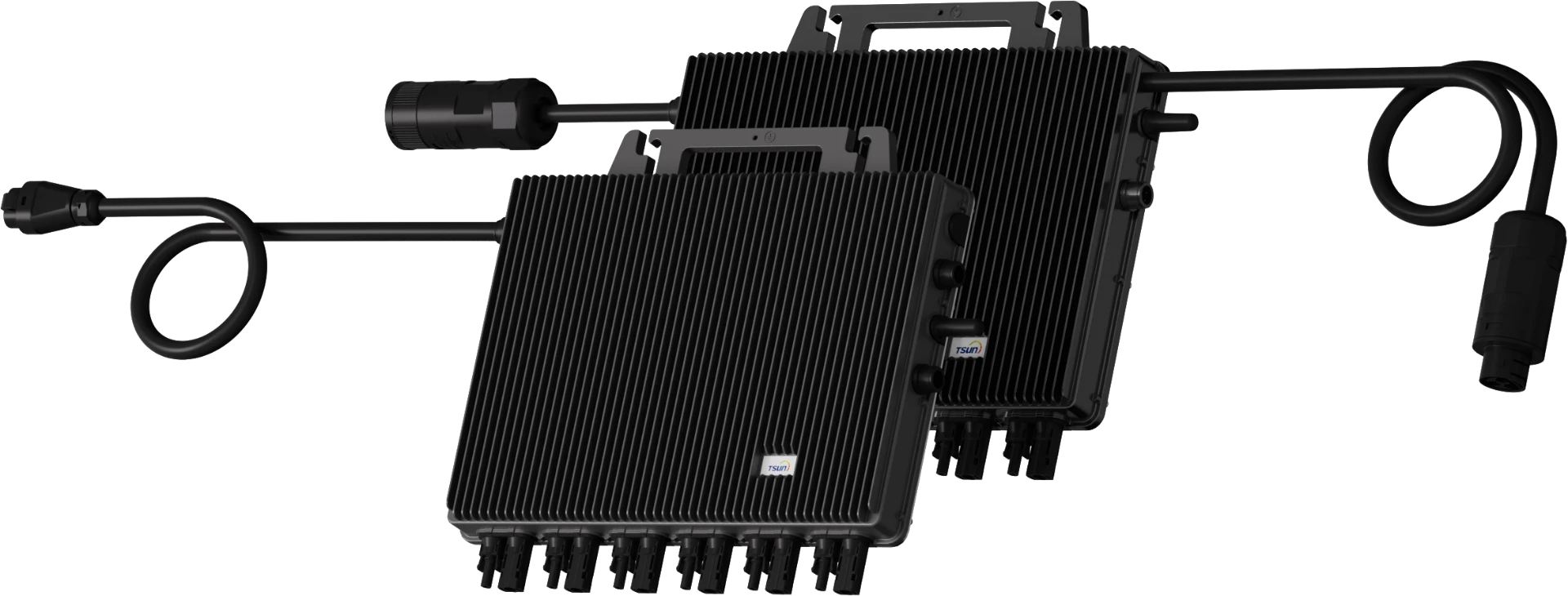
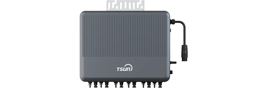
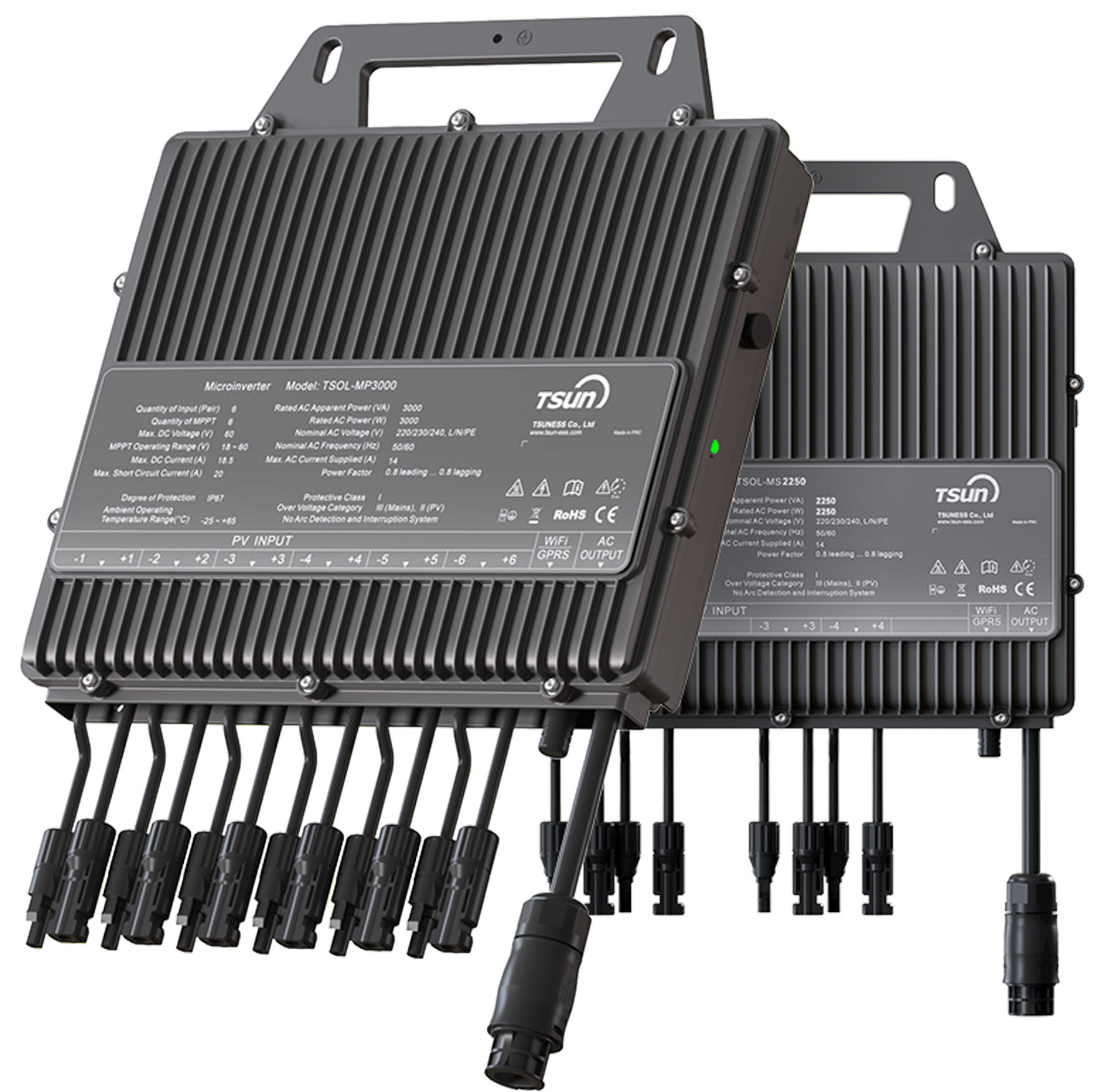
GEN3 Microinverter 2400W-3300W
|
Individual optimization, separate dedicated MPPT for each panel
peak efficiency of up to 97%
Guaranteed quality with standard 12 years warranty
Plug and Play installation, Easy to install
Casting design and glue-filling technology.
|
3. Product reliability and technical support
TSUN microinverters not only have advantages in communication, but their product design has also undergone rigorous testing and verification to ensure the stability and durability of the equipment in long-term operation. Whether in high temperatures, humidity, or other harsh environments, TSUN's microinverters can maintain efficient operation.
In addition, TSUN also provides customers with high-quality technical support and services. Whether during the installation, commissioning phase, or subsequent system maintenance, TSUN's technical team always provides customers with comprehensive support to help solve any technical problems and ensure the smooth operation of the system. Excellent customer service is also one of the key reasons why TSUN is highly trusted in the market.
Summary
In photovoltaic systems, different communication methods have their own unique advantages and applicable scenarios:
WiFi communication: low cost, easy installation, suitable for small photovoltaic systems, but poor signal stability, and greater environmental interference.
PLC communication: using existing power lines to transmit data, medium installation cost, suitable for small and medium-sized applications, but affected by power line noise, the signal stability is slightly weak.
Sub-1G communication: the transmission signal is relatively stable and less affected by interference. It is suitable for scenarios with large signal coverage and high stability requirements, and the installation complexity is medium.
RS485 communication: long transmission distance, extremely high stability, suitable for large industrial applications, but complex installation, requiring professional wiring and debugging.
According to diverse project requirements, the following options can be contemplated:
Small residential or commercial photovoltaic systems: WiFi modules are highly cost-effective, simple to install, and ideal for projects demanding rapid deployment.
Small and medium-sized projects: PLC or Sub-1G communication can offer superior stability and coverage, making them suitable for medium-sized systems.
Large industrial or photovoltaic power stations: RS485 stands as the optimal choice as it can provide the most stable long-distance communication and is appropriate for environments with stringent requirements for signal reliability and system complexity.
When choosing a communication method, one should thoroughly take into account the scale of the project, the installation environment, budget limitations, and the stability requirements of data transmission.
 LEARN DETAILS



 LEARN DETAILS
 LEARN DETAILS
 LEARN DETAILS
 LEARN DETAILS
 LEARN DETAILS



 Downloads
 Video Center
 Report Fault for Repair
 FAQS
FAQS Service Network
 Privacy Policy
 Contact us
 Monitoring


 LEARN MORE


